A simple model for wind effects of burning structures and topography on wildland–urban interface surface-fire propagation
Ronald G. Rehm A C and William (Ruddy) Mell BA RGR Consulting, Limited Liability Corporation and National Institute of Standards and Technology, Building 224, Room B260, 100 Bureau Drive, Gaithersburg, MD 20899, USA.
B National Institute of Standards and Technology, Building 224, Room B246, 100 Bureau Drive, Gaithersburg, MD 20899, USA.
C Corresponding author. Email: ronald.rehm@nist.gov
International Journal of Wildland Fire 18(3) 290-301 https://doi.org/10.1071/WF08087
Submitted: 29 May 2007 Accepted: 1 July 2008 Published: 28 May 2009
Abstract
The present paper presents a simple model to demonstrate the effect on grass-fire propagation of the winds induced by structural fires in a wildland–urban interface setting. The model combines an empirical formula for wind-driven grass-fire spread and a physics-based analytical solution to the Euler equations to determine the ground-level wind produced by the burning structure. The scaling of the wind is based on the heat release rate of the structural fire as well as other parameters. Also considered are an ambient wind and a topographical wind, assumed to be proportional to the ground slope. Data on grass and structure fires required by the model are discussed. Fire front propagation predicted by this model is illustrated by three examples: a front passing a single burning structure on flat terrain, a front passing a burning structure on a hill, and a front passing several burning structures. The model predicts that a fire front will be accelerated toward the burning structure upon approach and decelerated after passing the structure. Several burning structures multiply the effects of an individual burning structure.
Acknowledgements
The present research (R.G.R) was supported in part by NIST Contract Number SB1341–05-W-1003, Dr Anthony Hamins, Contract Monitor.
Albini FA (1984) Wildland fires. American Scientist 72, 590–597.
Cheney NP, Gould JS , Catchpole WR (1998) Prediction of fire spread in grasslands. International Journal of Wildland Fire 8, 1–13.
| Crossref | GoogleScholarGoogle Scholar |
Gustafson EJ, Hammer RB, Radeloff VC , Potts RS (2005) The relationship between environmental amenities and changing human settlement patterns between 1980 and 2000 in the Midwestern USA. Landscape Ecology 20, 773–789.
| Crossref | GoogleScholarGoogle Scholar |
McGrattan KB, Baum HR , Rehm RG (1996) Numerical simulation of smoke plumes from large oil fires. Atmospheric Environment 30, 4125–4136.
| Crossref | GoogleScholarGoogle Scholar | CAS |
Mell W, Jenkins MA, Gould J , Cheney P (2007) A physics-based approach to modeling grassland fires. International Journal of Wildland Fire 16, 1–22.
| Crossref | GoogleScholarGoogle Scholar |
Ohlemiller T , Corley D (1994) Heat release rate and induced wind field in a large scale fire. Combustion Science and Technology 97, 315–330.
| Crossref | GoogleScholarGoogle Scholar |
Radeloff VC, Hammer RB , Stewart SI (2005) Rural and suburban sprawl in the US Midwest from 1940 to 2000 and its relation to forest fragmentation. Conservation Biology 19(3), 793–805.
| Crossref | GoogleScholarGoogle Scholar |
Appendix
In this Appendix, Lagrangian equations are presented for determining the fire-front propagation on a specified surface or topography in the presence of burning structures. The governing equations are the ODEs describing the propagation of an element of the fire front along the surface:

The equations are given in vector form  , where
  are unit vectors in the x, y, z directions.
  is the rate of spread (ROS) vector of the fire front at the location (x, y, z), and are the components of the unit normal to the fire front directed toward the unburnt fuel. s is the arc length of the curve.
The linear relation given in Eqn 1 between the ROS and the local wind velocity is assumed. For a line of sufficient head width W and for very low moisture content of the grass, this reduces to:

where  and
and  with ROS0 = 0.165 [m s–1] and cf = 3.24. Then

For notational simplicity, we will not explicitly show the time dependency of these functions as we obtain the tangent and the normal vectors to the fire front. The tangent to this curve is determined by  and can be written as:

Define the normal vector to the fire front by the parameter n as follows:

 is determined by the requirement that the dot product of the normal and tangential vectors be zero:
Define the following quantities:

and

Then, we can write the unit normal vector to the fire front on the prescribed surface as follows:

At the wildland–urban interface, houses as well as wildland fuels can be burning. In this model, we account for three elementary wind fields, the ambient wind, a topographically induced wind and the entrainment wind produced by all burning structures. We assume that the total velocity at any location can then be determined by adding linearly the contributions of all the elementary wind fields. The total velocity locally is taken to be the sum of these velocity contributions:

We take for simplicity the horizontal components of the local ambient wind (Va,x, Va,y) to be uniform in space. Then, the z-component of the ambient wind is given by  .
.
In the absence of any ambient wind and over flat terrain, a fire front is found to propagate with the uniform ROS as discussed above. When there are topographical features, Z(x,y), but no ambient wind, it is found that the ROS of the fire front increases uphill and decreases downhill because of buoyancy effects. This observed behavior can be treated by defining a topographically induced horizontal velocity that is proportional to the gradient of the hill (Rothermel 1972). Here, we take this equivalent horizontal velocity to be given by the relations  and
and  , where α is a proportionality constant (Rothermel 1972). The z-component of the topographically induced velocity is given by
  .
.
For a fire front exposed to the velocity field generated by a single burning structure of HRR Q0, the characteristic length and velocity scales are D* and V* as discussed earlier. Let  denote the vector distance from the center of the structure to the element of the fire front. The velocity at this point will be where is the dimensionless velocity and is the length scale defined above, and the dimensionless vector distance,
  , is
, is  .
.
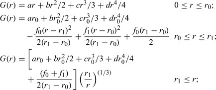
The detailed solution for the dimensionless velocity function at ground level, G(r) was obtained analytically by Baum and McCaffrey in terms of special functions. For computational purposes, however, this solution was replaced in the example calculations presented here by the functional form given below, which closely approximates the analytical solution:

where r0 = 0.8; r1 = 1.0; f0 = 0.407199; f1 = 0.045029; a = –2.39441; b = 11.2283; c = –13.6154; and d = 4.9468.
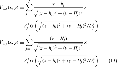
Therefore, for a single burning structure at (x = h, y = H), the induced horizontal entrainment velocity components at any point (x, y) are

The vertical component of the entrainment velocity is taken to be

The total entrainment from all of the burning structures is obtained by simple summation (Rehm 2006). If, for example, the jth structure has an entrainment velocity and a characteristic length scale determined by the heat release rate of the burning structure (as described in Rehm 2006), and if the location of the structure is given by x = hj, y = Hj, then the total entrainment velocity is given by

where we have assumed that the entrainment velocity from each burning structure is only dependent on the vector distance in a horizontal plane between the observational location (x, y) and the location of the burning structure.
Only the first two of the three vector-component equations for the fire-front spread need to be solved, as the front is constrained to the surface z = Z(x, y) (assuming that we can describe the surface explicitly in this form). The functional form for the surface is used to eliminate z in the component equations for x and y, yielding two ODEs for x(s, t) and y(s, t). These are solved as described below, and z is determined at (x, y) from the equation for the surface.
At each point, the fire front is advanced in the direction normal to the front at a speed determined by the local ROS for the fire. This ROS, in turn, depends on the wind speed at that location. For computational purposes, the fire front is discretized and then moved incrementally to its new location. We consider the fireline initially to be a straight line along the x-axis, running between –L and L and divide this interval into 2I panels each of length δ, where δ = 1/I. We start with an approximation to the normal ROS, and then numerically solve the governing equations. We use the MOL and a centered difference scheme for the spatial discretization at all interior nodes of the fire front. For the end nodes, we use a one-sided difference scheme with the neighboring interior node.


