Fire whirls induced by a line fire on a windward slope: a laboratory-scale study
Kuibin Zhou A B * , Yifan Wang A , Albert Simeoni B and Ruixing Dong AA
B
Abstract
Fire whirls are often reported to occur in wildland fires and can induce serious difficulties in firefighting by abruptly modifying fire behaviour, exposing firefighters and even causing casualties.
The aim of this study was to examine the formation of fire whirls on a windward slope.
Straight and V-shaped heated wires and burners were used to emulate fire spread fronts of various fire intensities. Different slope angles and ambient wind speeds were considered, to observe the formation and behaviour of fire whirls.
A fire whirl appeared over a straight-line fire in the presence of wind, and a couple of counter-rotating fire whirls appeared over the two flanks of a V-shaped line fire.
Two interaction regimes were experimentally observed and theoretically explained for the interaction of two fire whirls. We found that an effective wind speed instead of the local wind speed in sloped terrains can quantify the critical condition for the formation of fire whirls over line fires of different burning intensities.
A critical effective wind speed correlation that couples slope angle, burning intensity and radiative fraction of a line fire can predict fire whirl risk in wildland fire fighting.
Keywords: ambient wind, fire intensity, fire line, fire whirl, firefighting, line fire, slope steepness, vortex flow, V-shaped fire, windward slope.
Introduction
Extreme fire behaviour, characterised by rapid fire spread, intense burning, long-range fire spotting, fire whirl and unpredictable shifts etc., defines the new context of wildland fires (Castro Rego et al. 2018; Tedim et al. 2018). A fire whirl, also named a fire whirlwind, fire devil or fire tornado, is often reported to occur in wildland fires, due to the interaction between the burning flame front and the local wind field (Zhou 2018). It is not only related to the vortex containing flame but also to a whirl that appears in and around a fire containing smoke, hot gases, unburned fuel and ashes (Soma and Saito 1991). Fire whirls can remarkably increase the fire spread rate and burning rate (Countryman 1971) and have close relevance to extreme fire behaviour (Wang et al. 2017). Their appearance can result in serious difficulty in wildland firefighting (Countryman 1971) and induce great losses of life and property (Zhou 2018). Thus, the fire whirl phenomenon has occupied scientific and engineering research for decades, and is still a major concern.
The main questions about fire whirl include their formation condition and their combustion dynamics. However, formation condition has received less attention than combustion dynamics, as indicated in the recent review of Liu et al. (2021). Three essential conditions have been identified for the formation of fire whirls, i.e. a generating eddy, a fluid sink located within the eddy and some friction or drag offered to the movement of air near the ground (Byram and Martin 1970). However, the three conditions are too abstract to clarify the weather and terrain conditions that trigger different types of fire whirls. Accordingly, a concrete analysis has been suggested to clarify the formation condition and mechanism for a specific fire whirl (Zhou 2018; Zhou et al. 2019). A reduced-scale experiment has been successfully used to explore the open-field ambient wind condition for fire whirls generated in the wake of mass fires (Soma and Saito 1991), in the vicinity of L-shaped fires (Soma and Saito 1991; Kuwana et al. 2008), by the interaction of multiple fires (Soma and Saito 1991; Liu et al. 2007) and over a line fire (Kuwana et al. 2013; Zhou et al. 2014, 2016, 2019). However, all the works cited above only reconstructed a fire whirl happening for no slope, without considering the effect of slope.
A lot of field observations show that the most favourable condition for fire whirl occurrence is over a fire plume located near the lee side of the top of a steep slope with strong winds blowing over the ridgetop (Graham 2003). The formation mechanism of these fire whirls could relate to the eddies formed by the blocking effect of the ridge, combined with the wind shear when the upslope fire plume meets the cool opposing wind (Countryman 1971). Emori and Saito (1982) reproduced a leeward fire whirl in a reduced-scale experiment and used scaling laws to derive the critical wind speed that creates the appearance of the fire whirl. Moreover, numerical simulations of the leeward fire whirl examined the effect of the ambient wind speed, wind direction and lee slope steepness (Simpson et al. 2016). In addition, Chuah et al. (2011) experimentally studied the flame length of leeward fire whirls in a quasi-steady state on a 30° slope and suggested a dependence to the Rossby number instead of the Froude number. In short, the formation condition and mechanism, as well as the combustion dynamics, have been extensively examined for leeward fire whirls.
A fire whirl could also appear on a windward slope, as shown in a field experiment by Pinto et al. (2017). In lab experiments for upslope fires spreading under no wind, the fire front gradually transitioned from a U-shape to a V-shape as the slope value increased, and fire whirls were observed to move along the fire flanks towards the fire head on a 30° slope (Dupuy et al. 2011; Silvani et al. 2012, 2018). The V-shaped fire front could be influenced by the upslope wind due to the hot plume generated by smouldering behind the fire front. Until now, the available experimental studies did not lead to the quantification of the formation condition and combustion dynamics of windward fire whirls.
In this work, heated nickel–chromium wires and line fires located at a fixed location on a tilted platform are used to simulate a fire front spreading in the upslope direction. Straight and V-shaped linear wires, as well as line burners, were used in the tests. The V-shape stands for typical upslope fire fronts, whereas the straight-line shape only allows to examine one flank of a V-shaped fire front. In particular, the vortex flow over the wire is well similar to the fire whirl over the line burner, which indicates the validation and robustness of experimental design. To this end, we first discuss the fire whirl phenomenon generated under different configurations in terms of different slope angles and ambient wind speeds, and then the critical criterion that couples the ambient wind speed, the slope angle, the burning intensity and the radiative fraction is proposed for the fire whirl formation, finally followed by a discussion of the implications for wildland fire fighting in sloped terrains.
Experiments
Experimental setup
The experiments reproducing vortex flow or fire whirl phenomena were conducted using a setup that consisted of a mechanical wind wall, a tilting platform, a smoke generator and a laser, as well as a nickel–chromium wire heated by electricity or a line burner (Fig. 1). The nickel–chromium wire helps to produce the vortex flow, and the line burner is used to induce a fire whirl.
Schematic of the experimental setup. (a) Schematic of the experimental setup. Only the nickel–chromium wire is shown. (b) Gas burner system for generating line fires. (c) Layout of nickel–chromium wires. (d) Layout of line burners.
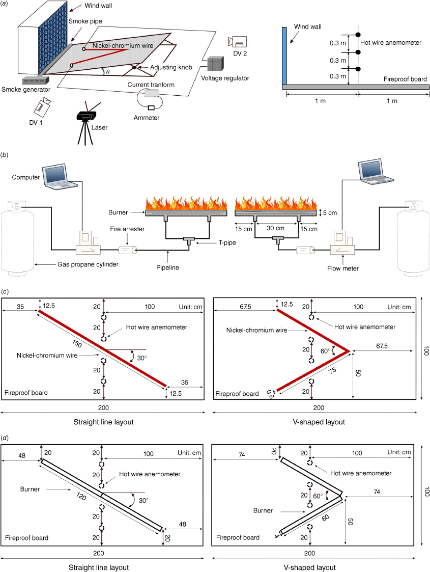
The wind wall consists of a plastic pipe stack, an axial flow fan, a power transducer and a frame. It has been described in details in previous work (Zhou et al. 2019). Only its key characteristics are repeated here. The power transducer has a frequency of 0–50 Hz with a 0.5 Hz resolution. The wind wall provides a uniform wind speed at its outlet, which has a 1 m × 1 m section. The tilting platform is made of a supporting frame, two adjusting knobs and a piece of fireproof board (Zhou et al. 2021). The smoke-tracing apparatus consists of a smoke generator and a steel pipe of 7.6 cm in diameter. The generator (1800 FOGGER, Guangzhou Lodi) produces smoke consisting of hot water vapour with particles of approximately 5 μm in diameter. The steel pipe holds nine holes with a diameter of 8 mm and an equal spacing of 10 cm. The smoke leaves the holes and follows the airflow created by the wind wall. The laser (model LWGL532-3-L of Laser wave, Peking) can produce a light of 532 nm that can make the smoke clearly visible in the zone of interest, because the light wavelength is much less than the diameter of smoke particle.
The electrical power for heating the nickel–chromium wire is controlled by a voltage regulator with an output of 0–300 V with 1 V resolution and a current transformer that reads a current of 0–25 A with a 0.1 A resolution (Zhou et al. 2019). The product of voltage and current is the heat release rate (Q̇) of the nickel–chromium wire. During the tests, the nickel–chromium wire is directly placed on the fireproof board (Fig. 1a).
The gas burner system consists of a propane gas cylinder, a flow meter, a fire arrester and a line burner connected by stainless pipes (Fig. 1b). Inside the gas burner, there is a thin ceramic fibre blanket at the bottom, one thick layer of glass beads of 3 mm in diameter in the middle and another thin ceramic fibre blanket at the top. The glass bead layer is nearly 5 cm in thickness and can completely reduce the momentum of the flow of propane generated by the cylinder. Linear holes are drilled through the fireproof board to place the liner burner. The burner top is flush with the upper surface of the fireproof board, and the gap between the hole and the burner rim is filled with plasticine. The flow meter (Alicat mass flow controller) is used to monitor the mass flow rate of propane with an accuracy of ±0.2% within a range of 0–50 standard litre per min (SLPM). The heat of combustion is 46.3 MJ/kg. The product of the mass flow rate and the heat of combustion of the fuel is the heat release rate (Q̇) of the line fire.
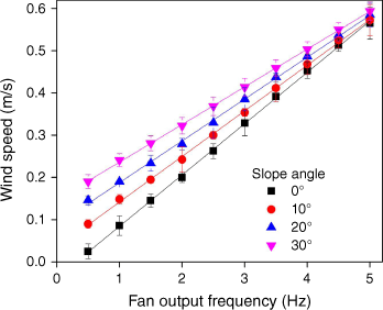
Constant temperature hot wire anemometers (HWAs, model 0963-00 of Kanomax Inc.) were placed 1 m away from the wind wall exit (Fig. 1a). Notice that the hot wire anemometer is at least 30 cm away from the fireproof board, i.e. outside the flow boundary layer. The wind velocity was measured at 12 different locations – over three rows by four columns in the vertical (Fig. 1a) and horizontal (Fig. 1c, d) directions, respectively – for four different slope angles. Neither hot air plumes nor fire plumes were generated during the measurement of the wind speed. The frequency of the HWA probe is 10 Hz. The average wind speed (Ua) over time and space is linearly plotted against the fan output frequency, as shown in Fig. 2. The slope angle increases the air flow velocity at the measuring points.
Average wind speed vs fan frequency. The error bar is the mean standard deviation of the flow velocities measured by the hot wire anemometer at 12 different locations.
Both the linear heat wire and the line burner were set to be straight and V-shaped, as shown in Fig. 1c, d, respectively. The wire was 150 cm in length and 0.8 cm in diameter, and the line burner was 120 cm in length and 4 cm in width. The attack angle is 30° for the straight wire and burner, and the angle at the tip is 60° for the V-shaped wire and burner. Fig. 1c, d show the relative position of the wire and the burner on the fireproof board, respectively. Table 1 shows the test conditions. θ is the inclined angle of the slope apparatus, I is the fireline intensity or the heat release rate per length, i.e. I = Q̇/l, and l is the wire or burner length.
| Layout types | Slope (θ) | I (kW/m) | Ua (m/s) | |
|---|---|---|---|---|
| Straight-line wire | 0° | 0.55, 0.63, 0.83, 0.89, 0.97 | 0.03, 0.09, 0.15, 0.20 | |
| 10° | 0.57, 0.63, 0.67, 0.79, 0.91 | 0.09, 0.15, 0.20, 0.24 | ||
| 30° | 0.63, 0.73, 0.86, 0.87, 0.92 | 0.20, 0.24, 0.32, 0.41 | ||
| Straight-line burner | 0° | 15, 20, 25, 30.1, 35.1 | 0.09, 0.24, 0.34, 0.46, 0.67 | |
| 10° | 15, 17.5, 20, 25, 30.1, 32.6 | 0.15, 0.24, 0.37, 0.49, 0.59 | ||
| 30° | 15, 20, 25, 30.1, 35.1 | 0.24, 0.32, 0.41, 0.50 | ||
| V-shaped line wire | 0° | 0.72, 0.97, 1.01, 1.21 | 0.03, 0.09, 0.15, 0.20 | |
| 10° | 0.94, 1.02, 1.13, 1.21 | 0.09, 0.15, 0.20, 0.24 | ||
| 20° | 0.95, 1.06, 1.21, 1.34 | 0.15, 0.20, 0.24, 0.28 | ||
| V-shaped line burner | 0° | 15, 20, 25, 30.1 | 0.09, 0.24, 0.34, 0.46, 0.67 | |
| 10° | 15, 20, 25, 30.1 | 0.15, 0.24, 0.37, 0.49, 0.59 | ||
| 30° | 15, 20, 25, 30.1 | 0.24, 0.32, 0.41, 0.50 |
General observations
Fig. 3 shows the vortex flow induced by the heated straight wire on a 30° slope. The simulated fire intensity is 628.9 W/m for the heated wire, and the wind speed is 0.20 m/s. A counterclockwise vortex can be observed away from or above the heated wire. The presence of ambient and upslope wind causes it to move from the windward end to the leeward end of the straight wire.
Photos of the formation and evolution of a vortex flow at relative times: (a) 0 s, (b) 2 s and (c) 4 s. Straight-line wire; θ = 30°; I = 628.9 W/m; Ua = 0.20 m/s.

Fig. 4 shows a fire whirl over a straight-line burner for a slope of 30°. The fire intensity is 30.1 kW/m, and the wind speed is 0.32 m/s. A fire whirl always appears at the leeward end of the line burner and rotates counterclockwise. It was observed that the spinning flame is perpendicular to the slope. This phenomenon can be explained by the Rossby number instead of the Froude number (Chuah et al. 2011).
Photos of fire whirl formation and evolution at the relative times: (a) 0 s, (b) 2 s and (c) 4 s. Straight-line burner; θ = 30°; I = 30.1 kW/m; Ua = 0.32 m/s.

Fig. 5 shows the vortex flow induced by the heated V-shaped wire on the slope of 10°. The simulated fire intensity is 1210 W/m for the heated wire, and the wind speed is 0.09 m/s. A pair of counterrotating vortices appears on the two flanks of the V-shaped wire. The counterclockwise and clockwise vortices can be observed away from and above the heated wire at the left and right flanks, respectively. The ambient and upslope wind causes them to move from the windward end to leeward end of the V-shaped wire. The behaviour of the counterclockwise vortex is similar to the behaviour of the vortex observed in Fig. 3.
Photos of vortex flow formation and evolution at the relative times: (a) 0 s, (b) 4 s and (c) 12 s. V-shaped line wire; θ = 10°; I = 1210 W/m; Ua = 0.09 m/s.

Fig. 6 shows the fire whirls over the V-shaped line burner for a 10° slope. The fire intensity is 30.1 kW/m and the wind speed is 0.24 m/s. Two counterrotating fire whirls appear first at the windward end of the V-shaped burner and then move along the two flanks of the burner to finally collide with each other and kill the vortex flow at the junction of the V-shaped burner. The fire whirls remain perpendicular to the slope surface (Fig. 6a, b), while the flame made from the merging of the two fire whirls inclines towards the slope surface (Fig. 6c).
Photos of fire whirl formation and evolution at the relative times: (a) 0 s, (b) 3 s and (c) 5 s. V-shaped line burner; θ = 10°; I = 30.1 kW/m; Ua = 0.24 m/s.

The heated wire can be used to model the vortex flow that could be the eddy source of the fire whirl, as indicated by the comparison of results between the straight or V-shaped wire and line burner, in Figs 3–6. Comparisons between Figs 3 and 4, as well as Figs 5 and 6, show that a larger fire intensity requires a larger wind speed to generate the vortex flow, independently of the configuration of the heated wire or the line burner. The fire whirl is easier to generate with V-shaped layout than with the straight layout, as indicated by lower wind speed for the same fire intensity in Figs 4 and 6. Anyway, all the four different configuration can generate the vortex flow or fire whirl under certain slope, fireline intensity and ambient wind speed conditions.
Results and discussion
Fire whirls generated under different configurations
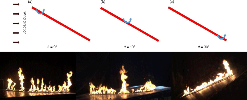
Fig. 7 shows the effect of slope on the behaviour of a vortex flow induced by the heated straight wire. The simulated fire intensity is 628.9 W/m, and the wind speed is 0.20 m/s. Only one counterclockwise vortex is observed in the flow field. As the slope angle increases, the most probable location of the vortex flow moves from the windward end to the leeward end of the heated wire. Notice that the vortex flow only can be visualised in the zone covered by smoke.
Fig. 8 shows the effect of slope on fire whirl behaviour over a straight-line burner. The fire intensity is 30.1 kW/m, and the wind speed is 0.24 m/s. The fire whirl rotates counterclockwise at different positions. Under no slope, most of fire whirls appear near the windward end of the line burner, whereas for a 10° slope, they start to form near the middle of the line burner. They could move downwind and upslope after the formation. However, the appearance of the fire whirl is always near the leeward end of the line burner when the slope angle reaches 30°.
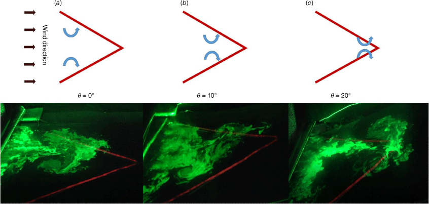
Fig. 9 shows the slope effect on the behaviour of double vortex flows induced by the heated V-shaped wire. The simulated fire intensity is 1210 W/m, and the wind speed is 0.15 m/s. One pair of counterrotating vortices is observed in the flow field. For no slope, the vortex pair appears near the entrance of the V-shaped wire. Its position reaches the middle and the junction of the V-shaped wire, for 10° and 20° slopes, respectively. As the slope angle increases to 30°, no vortex flow is observed. It is possible that the vortex pair could occur downwind away from the junction of V-shaped wire, but no smoke is present there to highlight them.
Fig. 10 shows the effect of slope on the behaviour of double fire whirls over the V-shaped line burner. The fire intensity is 30.1 kW/m, and the wind speed is 0.24 m/s. Double counterrotating fire whirls are observed on both flanks of the V-shaped fire, as long as the slope angle is not over 10°. As the slope angle increases, the position where the double fire whirls appear gradually nears the junction of the V-shaped burner. The double fire whirls merge at the joint in Fig. 10c, where the slope angle is 30°.
Behaviour of double fire whirls as the slope angle is (a) 0°, (b) 10° and (c) 30°. V-shaped line burner; I = 30.1 kW/m; Ua = 0.24 m/s.
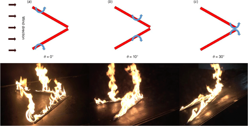
The double fire whirls interacted with each other due to the restriction of air entrainment by the flames. In addition, the vortex flow field generated by one fire whirl would impart the other fire whirl. As the slope angle increases, the spacing of the fire whirls over each flank decreases, enhancing the interaction.
Fig. 11 shows the formation and evolution of fire whirls over the V-shaped line burner for either no slope or a 10° slope. The wind speed is 0.24 m/s. The fire intensity is 20 kW/m on the left flank and 30.1 kW/m on the right flank. Only a counterclockwise fire whirl is observed on the right flank. The flames on the left flank seem to tilt towards the fire whirl located on the right flank, even though the wind direction is opposite to the direction where the flames are tilting. This behaviour indicates that the fire whirl can significantly alter the local flow field to complicate the flame behaviour in wildland fire. It is of great interest to stress that clockwise fire whirls appear on the left flank, when the fire intensity is 30.1 kW/m on the left flank and 20 kW/m on the right flank. In short, the fire whirl seems to occur on the flank with higher fire intensity.
Fig. 12 shows the formation and merging of double clockwise vortex flows induced by the heated V-shaped wire for a 10° slope. The fire intensity is 1210 W/m, and the wind speed is 0.15 m/s. The two vortex flows appear simultaneously on one flank of the V-shaped wire. The upstream vortex flow moves faster than the downstream one, so the spacing between two vortices gradually decreases, enhancing their interaction. They finally combine to form a more intense vortex flow.
Formation and merging of double clockwise vortex flows. V-shaped heated wires; θ = 10°; I = 1210 W/m; Ua = 0.15 m/s. (a) Photos at the relative times of 0, 2, 4 and 6 s. (b) Schematic diagram.
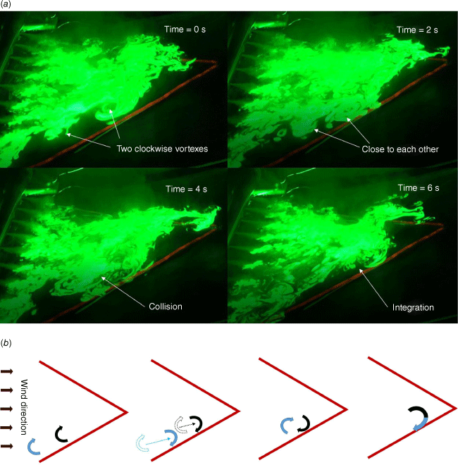
Fig. 13 shows the formation and merging of double clockwise fire whirls over the straight-line burner (Fig. 13a) and the V-shaped line for a 10° slope (Fig. 13b). Note that the two fire whirls only appear on the left flank of the V-shaped burner. As observed in Fig. 12, the two fire whirls combine to generate a more intense one. In the process of closing up and merging, the interaction between two clockwise whirls creates two opposite forces acting on the two rotating flames, respectively. Note that two point vortices can revolve around a centre if they have the same direction of rotation (Zhou et al. 2014). In addition, the bottom of the fire whirl is always over the burner, and the flame restricts the air entrainment in the gap between the double fire whirls. Consequently, the two fire whirls revolve around and lean toward each other during the merging process.
Photos of the formation and merging of double fire whirls. θ = 10°. (a) Straight-line burner and Ua = 0.15 m/s, I = 30.1 kW/m. (b) V-shaped line burner and Ua = 0.24 m/s, I = 30.1 kW/m on the left flank and 20 kW/m on the right flank.
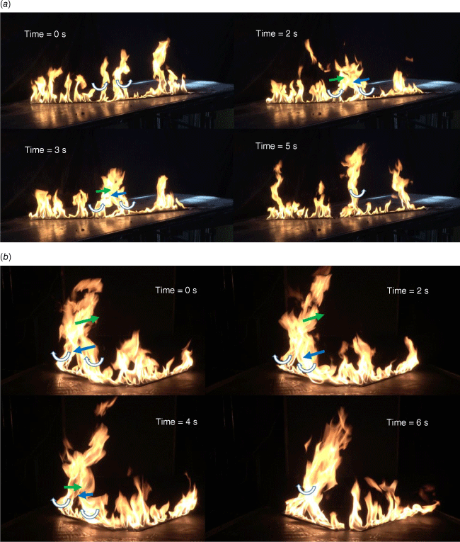
Figs 14 and 15 show the possible merging of double fire whirls at the junction of the V-shaped burner. The double fire whirls rotate oppositely on both flanks of the burner. When the two fire whirls move along each flank and simultaneously reach the junction of the burner for no slope (Fig. 14a) or a 10° slope (Fig. 6), they combine to form a large flame with no rotation. However, for a 30° slope, the two fire whirls simultaneously generate near the junction of the burner and then merge at the junction (Fig. 14b). The fire whirls that periodically roll along the two flanks toward to the junction of the burner are similar to those observed for a fire spreading on a 30° slope (Silvani et al. 2012). This highlights the fact that the V-shaped burner is a good tool to simulate fire spread over a slope. Even though the upslope fire spread experiment had no ambient wind (Dupuy et al. 2011; Silvani et al. 2012), the wind induced along the slope by the hot plume (generated by smouldering inside the burnt area located after the fire front) could play a role similar to the imposed ambient wind in this paper.
Critical wind speed of vortex flow or fire whirl formation
The critical wind speed is an important parameter to describe the formation of fire whirls, and it therefore receives a lot of attention in the case of line fires (Kuwana et al. 2008, 2013; Zhou et al. 2014, 2016, 2019). The Froude number theory indicates that the critical wind speed should be proportional to the upward velocity of the fire plume, i.e.
where Uc is the wind speed in a critical state, g the gravitational acceleration and H the flame length before the formation of the fire whirl (Kuwana et al. 2013). Zhou et al. (2014, 2016) expressed H as the mean flame height of the line fire in still air. Accordingly, H can be calculated by the flame height correlation of Yuan and Cox (1996), i.e.
where w = 0.8 cm and 4 cm are the widths of the wire and burner, respectively. In addition, ρa, cp,a, and Ta are the ambient air density and heat capacity at constant pressure and temperature, respectively. The following values were used: ρa = 1.29 kg/m3, cp,a = 1.004 kJ/kg-K and Ta = 283 K. Combining Eqns 1 and 2 yields
where I* = I/ρacp.aTag1/2w3/2 is the dimensionless fire intensity and A is a dimensionless coefficient that depends on data fitting. Two wind velocities can be used to test the validity of Eqn 3. One is the ambient wind speed measured by the HWA when no heat is released, and the other is the effective wind speed coupling the measured wind speed and the slope-induced wind. The slope-induced wind results from the asymmetric air entrainment of fire plume along the slope direction.
The ambient wind speed measured by the HWA for a cold flow (Fig. 2) is plotted against the dimensionless fire intensity, in order to determine coefficient A in Eqn 3. Then the effect of the slope angle on A can be quantified in detail under different arrangements of nickel–chromium wires or line burners.
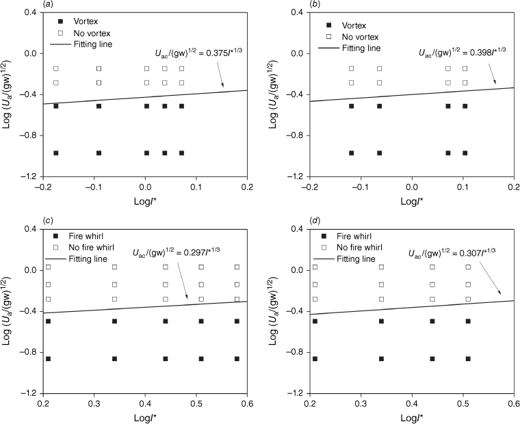
Fig. 15 shows the experimental phenomenon of fire whirl (vortex) and no fire whirl (vortex) with no slope, in terms of the dimensionless measured wind speed versus the dimensionless fire intensity. A critical fitting line is plotted to distinguish between fire whirl (vortex flow) and no fire whirl (vortex flow) using Eqn 3. As shown in Fig. 15a–c, the coefficient of A is 0.375, 0.398, 0.297 and 0.307, for the straight and V-shaped line wires and line burners, respectively. The average and standard error of A is 0.344 ± 0.050. The relative error of A is 14.53%. The coefficient of the straight configuration is lower than the coefficient of the V-shaped configuration, independently of using a heated wire or a line burner. The interaction of the upward plume with the two flanks of the V-shaped configuration increases the upward velocity, so it requires a larger critical wind speed to trigger a fire whirl. The heated wires yield a larger coefficient than the line burners, independently of the straight and V-shaped configurations. This could be a result of the higher radiation loss for the line fire than for the heated air flow over the wire.
Fig. 16 shows the experimental data for fire whirl (vortex flow) and no fire whirl (vortex flow) under a 10° slope angle. Eqn 3 is also used to plot the critical line that distinguishes between fire whirl and no fire whirl. A is 0.638, 0.556, 0.508 and 0.487, for the straight and V-shaped line wires and line burners, respectively. The average and standard error is 0.547 ± 0.067, and relative error is 12.25%. The coefficients of the heated wires are still slightly larger than those of the line burners, similarly as for those under no slope. However, A under the 10o slope angle is much larger than that under no slope, for the local air flow velocity is used for data fitting and increases as the slope angle increases (Fig. 2). Obviously, the local air flow velocity does not consider the coupled effect of fire and slope.
Dimensionless ambient wind speed vs dimensionless fire intensity for θ = 10°: (a) straight-line wire, (b) V-shaped line wire, (c) straight-line burner and (d) V-shaped line burner.
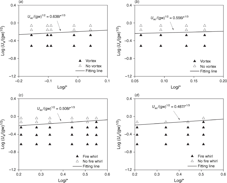
Fig. 17 shows the experimental data for fire whirl (vortex flow) and no fire whirl (vortex flow) under 20° (Fig. 17b) and 30° slope angles (Fig. 17a, c, d). The average and standard error for A is 0.641 ± 0.320 at a slope angle of 30°. The mean coefficient is not well defined, for the relative error reaches 50%. For the 30° slope, A in Eqn 3 for the heated wire is twice as large as the one for the line burner. Besides a greater radiation loss for the line fire, the slope-induced wind is likely another contributing factor. This is confirmed by the larger fire intensity of line fires compared with the simulated fire intensity of heated wires in Table 1, indicating a much larger slope-induced wind by line fires at high slope degrees. A larger slope-induced wind would require a lesser contribution of the ambient wind speed for the formation of a fire whirl, so it would reduce the value of A in Eqn 3 if only the ambient wind speed is considered for data fitting. Recall that the fire vortices moved along the two fire flanks towards the fire head in the 30° upslope fire tests under no ambient wind (Dupuy et al. 2011).
Nelson (2002) proposed a trigonometric method to couple the ambient wind speed and the upslope component of the buoyant velocity of the fire, in order to derive an effective wind speed. For the experimental setup and test conditions in this work, the effective wind speed (Ue) can be expressed by
where Ua,θ=0 is the ambient wind speed measured under no slope (see the data of θ = 0° in Fig. 2), and Ub represents the velocity at which the fire plume rises vertically due to buoyancy under no slope. The velocity Ub can be quantified by (Nelson 2002)
where Ic is the convective fire intensity given by
where χr is the radiative fraction, i.e. the ratio of the total radiant energy escaping from the fire plume or hot plume to the total heat release rate. An average value of the radiative fraction for the propane line fires could be 0.3 (Zhou and Simeoni 2022), but it should be nearly zero for the hot air plume over the heated wire. Eqn 4 yields Ue = Ua when the slope angle is zero. In Fig. 15, the Ua in the dimensionless wind speed can be replaced by the Ue to directly show the dimensionless effective wind speed versus dimensionless fire intensity.
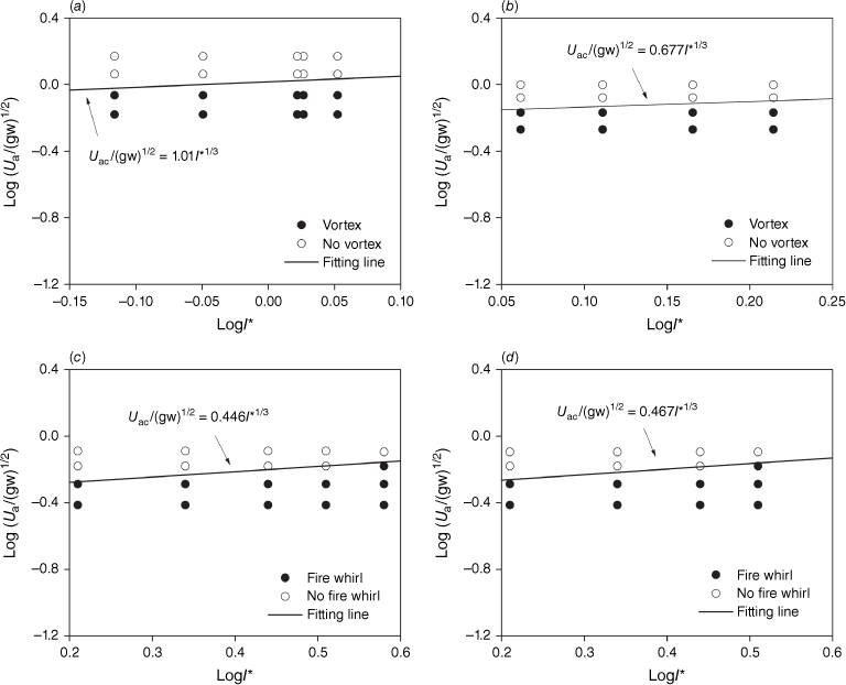
Fig. 18 shows the experimental data for fire whirl (vortex flow) and no fire whirl (vortex flow) in terms of the dimensionless efficient wind speed versus the dimensionless fire intensity, under a 10° slope. The data fitting for A in Eqn 3 provides the values 0.640, 0.583, 0.623 and 0.601, for the straight and V-shaped line wires and fires, respectively. The slope angle considerably increases the value of A for line fires, but has little effect on line wires, as indicated by the comparison between A in Figs 16 and 18. The reason for this is that how much A increases due to the upslope wind depends on the magnitude of fire intensity. The average and standard error is 0.612 ± 0.025 and the relative error is 4.08%, which is lower than 12.25% when using the ambient wind speed for data fitting.
Dimensionless efficient wind speed vs dimensionless fire intensity for θ = 10°: (a) straight-line wire, (b) V-shaped line wire, (c) straight-line burner and (d) V-shaped line burner.
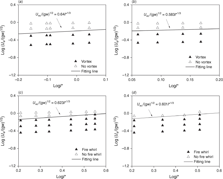
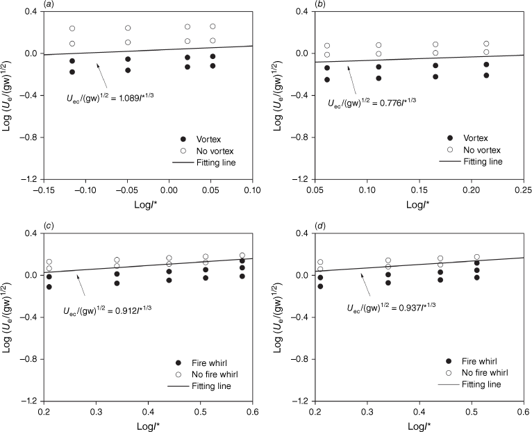
Fig. 19 shows the experimental data for fire whirl (vortex flow) and no fire whirl (vortex flow) in terms of the dimensionless efficient wind speed versus the dimensionless fire intensity, for 20° or 30° slopes. The slope angle significantly affects the value of A for line fires, as indicated by comparing A in Figs 17 and 19. For a 30° slope angle, A in Eqn 3 is determined to be 1.089, 0.912 and 0.937, for the straight-line wire, straight and V-shaped line burners, respectively. The average and standard error is 0.979 ± 0.096 and the relative error is 9.81%, whereas this last error was 50% when using the ambient wind speed.
Dimensionless efficient wind speed vs dimensionless fire intensity: (a) straight-line wire and θ = 30°, (b) V-shaped line wire and θ = 20°, (c) straight-line burner and θ = 30° and (d) V-shaped line burner and θ = 30°.
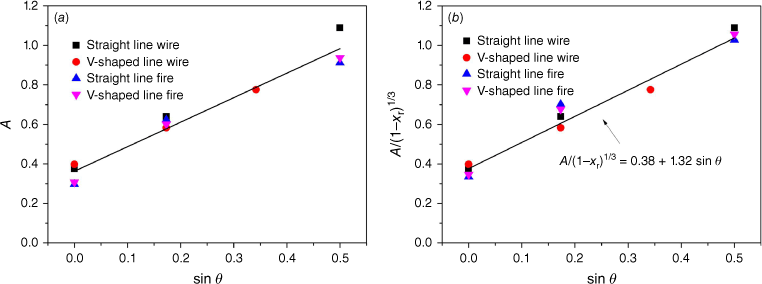
The coefficient A can be correlated with the slope angle, as shown in Fig. 20a. A seems to increase linearly as the sine of the slope angle increases. However, the value of A scatters to show a considerable difference between the heated wire and the line burner. It should be noted that Eqn 2 was used to quantify the hot air plume and the fire plume, but it does not consider the large difference in radiation loss between them. When using the convective fire intensity instead of the fire intensity in Eqn 2, and plotting A/(1−χr)1/3 against the sine of slope angle (Fig. 20b), the data fitting gives
Obviously, the data points collapse better around the fitting line when the radiative fraction is considered, as indicated by the comparison between Fig. 20a, b. Combining Eqns 3 and 7 results in the critical effective wind speed, i.e.
Eqns 4–6 and 8 can help to estimate the coupled effect of the ambient wind speed, slope angle, fire intensity and radiative fraction on the formation of the fire whirl vortex.
Coefficient A (Eqn 3) value vs slope angle: (a) without and (b) with consideration on the radiation loss.
Implication for wildland fire fighting in sloped terrains
Fire whirl is a phenomenon of considerable importance to firefighters, so they should learn to manage the risk posed by fire whirls during fire suppression operations. A fire intensity of 1730 kW/m is suggested as a threshold for fire suppression efficiency in wildland fires; this figure corresponds to a flame length of 2.4 m in average for fire fronts (Andrews and Rothermel 1982). In later research (Alexander and Cole 1995; Hirsch and Martell 1996; Tedim et al. 2018), 2000, 4000 and 10 000 kW/m were used as thresholds of moderately, very and extremely difficult to control, respectively. However, fire whirls generate much larger flame lengths and temperature than general fire fronts, even for the same fire intensity (Liu et al. 2021) and also a larger radiative fraction (Zhou et al. 2011; Wang et al. 2017). In addition, a fire whirl also increases the burning rate of solid or liquid fuels (Martin et al. 1976; Zhou et al. 2013). Because fire whirls are expected to also increase the burning rate of vegetation, the threshold for fire suppression efficiency could significantly decrease in their presence in the fire line, decreasing these thresholds.
For example, Fig. 21 shows the variation of the critical effective wind speed and the critical ambient wind speed with the slope angle, using Eqns 4–6 and 8, for a linear fire front propagating across the surface fuel, shrub or forest crown. An average radiative fraction of 9.7% is measured for the flame from burning pine needle in the fireline intensity range of 40–171 kW/m (Morandini et al. 2013), and its average is 17% for mixed-oak forest surface fires of 200–1000 kW/m fireline intensity (Kremens et al. 2012). Note that the critical ambient wind speed should be the one defined for no slope and far away from any sloped terrain, as indicated in Eqn 4. As shown, the increase of radiative fraction in the range of interest little decreases the critical wind speed for the fire whirl formation in wildland fires.
Critical wind speed vs slope angle: effective wind speed for the radiative fraction of (a) 9.7% and (b) 17%, and ambient wind speed for the radiative fraction of (c) 9.7% and (d) 17%.
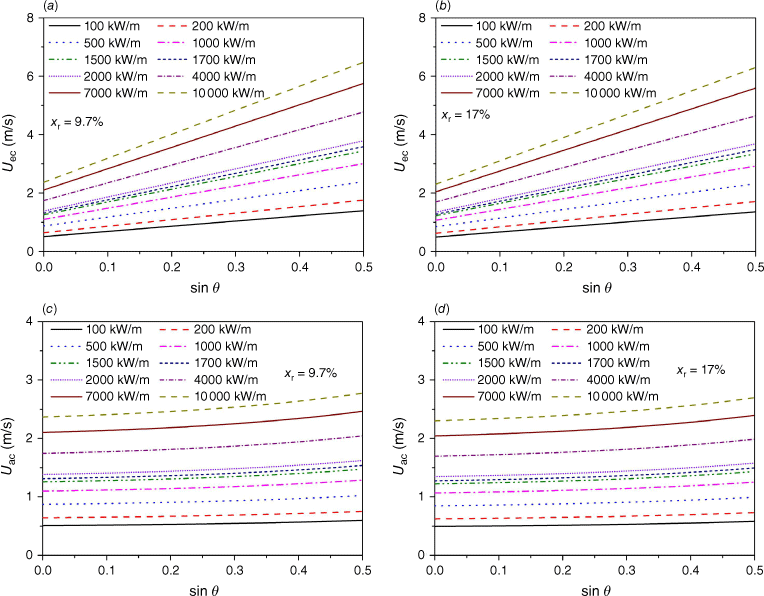
As shown in Fig. 21, both the effective and ambient wind speeds necessary for the occurrence of fire whirls increase as the fire intensity increases. The effective wind speed significantly increases as the slope angle increases, but the critical ambient wind speed shows only a moderate increase. Naturally, as the slope angle increases, the slope-induced wind gradually plays a greater role in the effective wind speed needed for the occurrence of fire whirls. It should be noted that the contribution of the heat generated by smouldering to the slope-induced wind has not been captured by the experiments and therefore, it is not included in the fitting correlation of Eqn 8. Accordingly, the critical ambient wind speed, necessary for the occurrence of fire whirls in actual wildland fire spread, should be lower than the one predicted in Fig. 21b. This figure also indicates that for a wildfire spreading along a slope, a constant ambient wind could trigger the critical state as the slope steepness increases, altering the rate of spread of the fire and the fire intensity.
Conclusions
This paper presents an experimental platform consisting of a mechanical wind wall and either a nickel-heated wire or a line burner over a tilted platform. This setup allows the study of the formation conditions and flame behaviour of a fire whirl induced by an upslope fire front under a cross wind. The effect of slope on the appearance of fire whirls has been discussed in detail. The major findings include:
A fire whirl (vortex flow) appears over a straight-line burner (heated wire) on a windward slope in the presence of ambient wind, and a couple of counterrotating fire whirls (vortex flows) appear over the two flanks of a V-shaped line fire (heated wire). The hot plume over the heated wire can represent a fire plume displaying formation conditions for a vortex flow similar to the ones encountered for a fire whirl.
The most probable position of a fire whirl gradually moves along the line burner in the upslope direction, as the slope increases. In particular, the fire whirl mostly appears at the leeward end of the line burner when the slope angle is 30°.
Two merging regimes are observed for the interaction of two fire whirls. One regime is for fire whirls rotating in the same direction over a straight-line fire or over one flank of a V-shaped line fire. The other regime is the convergence and merging at the junction of a V-shaped line burner for two counterrotating fire whirls appearing over the two flanks of the fire. In addition, when the two flanks have different fire intensities, a fire whirl only appears over the flank with higher fire intensity.
The local wind speed in sloped terrains cannot adequately quantify the critical wind speed for the formation of fire whirls over line fires of different burning intensities. Indeed, the slope-induced wind significantly increases as the fire intensity and the slope angle increase.
An effective wind speed coupling the ambient wind speed and the upslope wind is tested to well quantify the formation conditions of fire whirl. Data fitting gives a good correlation that combines the critical effective wind speed, slope angle and burning intensity, along with the radiative fraction of the line fire. The correlation can help to predict the fire whirl risk for wildland firefighting in sloped terrains.
In actual upslope fire spread, a large area of smouldering combustion can exist behind a linear fire front. The effect of the hot plume generated by smouldering on a fire whirl and its generation condition should be considered in future experiments. In addition, comparatively large-scale or field-scale studies should be introduced to confirm the above findings.
Conflicts of interest
Albert Simeoni is an Associate Editor of International Journal of Wildland Fire but was blinded from the peer-review process for this paper. The authors declare no conflicts of interest.
Declaration of funding
This research was supported by the support from the National Natural Science Foundation of China (51506082 and 51876088). KZ acknowledges the support from the Six Talent Peaks Project of Jiangsu Province of China under Grant no. XNYQC-005 and the support from WPI during the visit in August, 2023.
References
Alexander ME, Cole FV (1995) Predicting and interpreting fire intensities in Alaskan black spruce forests using the Canadian system of fire danger rating. In ‘Managing Forests to Meet People’s Needs: Proceedings of 1994 Society of American Foresters/Canadian Institute of Forestry Convention’. pp. 185–192. (Society of American Foresters: Bethesda, Maryland)
Byram G, Martin R (1970) The modeling of fire whirlwinds. Forest Science 16, 386-399.
| Google Scholar |
Castro Rego FMC, Moreno Rodríguez JM, Vallejo Calzada VR, Xanthopoulos G (2018) Europe in a new wildfire context. In ‘Forest Fires - Sparking firesmart policies in the EU’. (Ed N Faivre). Publications Office of the European Union: Luxembourg. 10.2777/181450
Chuah KH, Kuwana K, Saito K, Williams FA (2011) Inclined fire whirls. Proceedings of the Combustion Institute 33, 2417-2424.
| Crossref | Google Scholar |
Dupuy J-L, Maréchal J, Portier D, Valette J-C (2011) The effects of slope and fuel bed width on laboratory fire behaviour. International Journal of Wildland Fire 20, 272-288.
| Crossref | Google Scholar |
Emori RI, Saito K (1982) Model experiment of hazardous forest fire whirl. Fire Technology 18, 319-327.
| Crossref | Google Scholar |
Graham HE (2003) Fire whirlwind formation as favored by topography and upper winds. Fire Management Today 63, 59-62.
| Google Scholar |
Hirsch K, Martell D (1996) A Review of Initial Attack Fire Crew Productivity and Effectiveness. International Journal of Wildland Fire 6, 199-215.
| Crossref | Google Scholar |
Kremens RL, Dickinson MB, Bova AS (2012) Radiant flux density, energy density and fuel consumption in mixed-oak forest surface fires. International Journal of Wildland Fire 21, 722-730.
| Crossref | Google Scholar |
Kuwana K, Sekimoto K, Saito K, Williams FA (2008) Scaling fire whirls. Fire Safety Journal 43, 252-257.
| Crossref | Google Scholar |
Kuwana K, Sekimoto K, Minami T, Tashiro T, Saito K (2013) Scale-model experiments of moving fire whirl over a line fire. Proceedings of the Combustion Institute 34, 2625-2631.
| Crossref | Google Scholar |
Liu N, Liu Q, Deng Z, Kohyu S, Zhu J (2007) Burn-out time data analysis on interaction effects among multiple fires in fire arrays. Proceedings of the Combustion Institute 31, 2589-2597.
| Crossref | Google Scholar |
Liu N, Lei J, Gao W, Chen H, Xie X (2021) Combustion dynamics of large-scale wildfires. Proceedings of the Combustion Institute 38, 157-198.
| Crossref | Google Scholar |
Martin RE, Pendleton DW, Burgess W (1976) Effect of fire whirlwind formation on solid fuel burning rates. Fire Technology 12, 33-40.
| Crossref | Google Scholar |
Morandini F, Perez-Ramirez Y, Tihay V, Santoni P-A, Barboni T (2013) Radiant, convective and heat release characterization of vegetation fire. International Journal of Thermal Sciences 70, 83-91.
| Crossref | Google Scholar |
Nelson RM, Jr (2002) An effective wind speed for models of fire spread. International Journal of Wildland Fire 11, 153-161.
| Crossref | Google Scholar |
Pinto C, Viegas D, Almeida M, Raposo J (2017) Fire whirls in forest fires: An experimental analysis. Fire Safety Journal 87, 37-48.
| Crossref | Google Scholar |
Silvani X, Morandini F, Dupuy J-L (2012) Effects of slope on fire spread observed through video images and multiple-point thermal measurements. Experimental Thermal and Fluid Science 41, 99-111.
| Crossref | Google Scholar |
Silvani X, Morandini F, Dupuy JL, Susset A, Vernet R, Lambert O (2018) Measuring velocity field and heat transfer during natural fire spread over large inclinable bench. Experimental Thermal and Fluid Science 92, 184-201.
| Crossref | Google Scholar |
Simpson CC, Sharples JJ, Evans JP (2016) Sensitivity of atypical lateral fire spread to wind and slope. Geophysical Research Letters 43, 1744-1751.
| Crossref | Google Scholar |
Soma S, Saito K (1991) Reconstruction of fire whirls using scale models. Combustion and Flame 86, 269-284.
| Crossref | Google Scholar |
Tedim F, Leone V, Amraoui M, Bouillon C, Coughlan MR, Delogu GM, Fernandes PM, Ferreira C, McCaffrey S, McGee TK, Parente J, Paton D, Pereira MG, Ribeiro LM, Viegas DX, Xanthopoulos G (2018) Defining Extreme Wildfire Events: Difficulties, Challenges, and Impacts. Fire 1, 9.
| Crossref | Google Scholar |
Wang P, Liu N, Bai Y, Zhang L, Satoh K, Liu X (2017) An experimental study on thermal radiation of fire whirl. International Journal of Wildland Fire 26, 693-705.
| Crossref | Google Scholar |
Yuan L-M, Cox G (1996) An experimental study of some line fires. Fire Safety Journal 27, 123-139.
| Crossref | Google Scholar |
Zhou K (2018) Fire Whirls. In ‘Encyclopedia of Wildfires and Wildland-Urban Interface (WUI) Fires’. (Ed. SL Manzello) pp. 1–9. (Springer International Publishing: Cham) 10.1007/978-3-319-51727-8_23-1
Zhou K, Simeoni A (2022) An analytical model for predicting the flame length of fire lines and tree crown scorching. International Journal of Wildland Fire 31, 240-254.
| Crossref | Google Scholar |
Zhou K, Liu N, Satoh K (2011) Experimental research on burning rate, vertical velocity and radiation of medium-scale fire whirls. In ‘Fire safety science - proceedings of the tenth international symposium’. (Ed. M Spearpoint) pp. 681–691. (International Association for Fire Safety Science: Colleage Park, MD) 10.3801/IAFSS.FSS.10-681
Zhou K, Liu N, Lozano JS, Shan Y, Yao B, Satoh K (2013) Effect of flow circulation on combustion dynamics of fire whirl. Proceedings of the Combustion Institute 34, 2617-2624.
| Crossref | Google Scholar |
Zhou K, Liu N, Yin P, Yuan X, Jiang J (2014) Fire whirl due to interaction between line fire and cross wind. In ‘Fire Safety Science - Proceedings of the Eleventh International Symposium’. (Ed. Pv Hees) pp. 1420–1429. (International Association for Fire Safety Science: Canterbury, New Zealand) 10.3801/IAFSS.FSS.11-1420
Zhou K, Liu N, Yuan X (2016) Effect of Wind on Fire Whirl over a Line Fire. Fire Technology 52, 865-875.
| Crossref | Google Scholar |
Zhou K, Qian J, Qin X, Wang Z (2019) Thermally-driven vortex resulting from the linear heat wires of different shapes under cross wind. Applied Thermal Engineering 163, 114495.
| Crossref | Google Scholar |
Zhou K, Zhang L, Huang M, Zhou M, Wang C (2021) Experimental study on flame interaction and geometrical features of two identical fires on a slope. Fire Safety Journal 126, 103463.
| Crossref | Google Scholar |


