

Low-temperature Synthesis of Nanocrystalline LiNi0.5Mn1.5O4 and its Application as Cathode Material in High-power Li-ion Batteries
Shafiq Ullah A , Fiaz Ahmed B , Amin Badshah A D , Ataf Ali Altaf C , Ramsha Raza B , Bhajan Lal A and Rizwan Hussain BA Department of Chemistry, Quaid-i-Azam University, 45320, Islamabad, Pakistan.
B National Engineering and Scientific Commission, 44000, Islamabad, Pakistan.
C Department of Chemistry, Bahauddin Zakariya University Sahiwal Campus, 57000, Sahiwal, Pakistan.
D Corresponding author. Email: aminbadshah@yahoo.com
Australian Journal of Chemistry 67(2) 289-294 https://doi.org/10.1071/CH13442
Submitted: 27 August 2013 Accepted: 7 October 2013 Published: 21 November 2013
Abstract
Nickel-doped lithium manganate spinels are a potential material for future energy storage owing to high cell potential and low price. Phase-pure spinels are difficult to prepare by conventional solid-state synthesis methods owing to loss of oxygen from the crystal lattice at high temperature (~800°C). Loss of oxygen causes Jahn–Teller distortion and Mn4+ is converted into Mn3+, which results in undesired double-plateau discharge and reduction in capacity and stability of the material. In this study, nanocrystalline phase-pure LiNi0.5Mn1.5O4 was prepared by co-precipitation with cyclohexylamine followed by calcination at a low temperature of 500°C. X-ray diffraction studies confirmed that a highly crystalline face-centred cubic product is formed with F-d3m space group. Scanning electron microscopy and transmission electron microscope studies confirmed that the particles are in the nano range with a porous structure. The as-prepared LiNi0.5Mn1.5O4 showed a high initial specific capacity (up to 130 mA h g–1) and retained up to 120 mA h g–1 up to 50 cycles. The material has high conductivity and remains stable up to a 20-C discharge rate.
Introduction
Development of alternative energy resources for vehicular application is a key area of research due to diminishing fossil fuels and rising environmental concerns.[1–3] Research efforts are focussed on the field of solar cells,[4] fuel cells,[5] and batteries[6] as an energy source for electric and hybrid vehicles. All these technologies require advanced rechargeable batteries for energy storage and balancing. In recent years, the lithium ion has become the most popular rechargeable battery technology for consumer and portable electronics. The key features of lithium-ion batteries are low self-discharge, and high energy and power densities with a wide range of operating temperatures.[7–9] These batteries are based on the ‘rocking’ of lithium ions between the anode and cathode.[10] These batteries utilize carbon as anode and transition metal oxides as cathode material to host the lithium ions during the charge–discharge process.[11] Various cathode materials include layered lithium cobaltates, olivine lithium iron phosphates, and spinel lithium manganates.[12] Among these, lithium manganates are considered most suitable for electric vehicles owing to their low price, ease of preparation, and environmentally friendly nature.[13–17] Lithium manganates in their current state cannot meet the power and energy density requirements of the electric vehicle market.[18] Various efforts have been made to increase the power and energy densities of lithium manganate spinels by coating them with carbonaceous materials, doping with metals and non-metals, and preparation of nanostructures.[19,20] Among these, the nanoscale materials have led to a tremendous increase in the specific energy density but electrical conductivity remains the key problem.[21] Various efforts have been made to dope lithium manganates with transition metals such as cobalt, nickel, chromium, and copper to get high-voltage material that will lead to improved power density.[22,23] Among these, nickel-doped lithium manganates have gathered the most interest due to a high cell potential of 4.8 V, better electrical conductivity, and good cyclability. Coupling of nanoscale synthesis with nickel doping has resulted in a remarkable increase in the energy and power densities.[24–28] Lack of a simple synthesis method and high-potential-resistance electrolytes are the two major hurdles in the commercialization of nickel-doped lithium manganates.[29] Various efforts have been made to develop a simple and efficient method for the preparation of LiNi0.5Mn1.5O4. These include solid-state, solution-phase, sol-gel, spray pyrolysis, thin-film, molten-salt, and combustion methods.[30–42] In ideal LiNi0.5Mn1.5O4, a redox process occurs by insertion–de-insertion of the lithium ion into the 8a site of the crystal lattice with oxidation–reduction of the Ni2+/Ni4+ couple. In a perfect LiNi0.5Mn1.5O4 crystal lattice, nickel should be in the +2 and manganese in the +4 oxidation state. The solid-state process involves high-temperature treatments, which result in loss of oxygen from the lattice and cause Jahn–Teller distortion. This causes reduction of Mn4+ to Mn3+, which results in the appearance of a second undesired discharge plateau at 4 V and a decrease in overall energy and power density.[43–54] In the present work, we have synthesized phase-pure LiNi0.5Mn1.5O4 at low temperature. The low calcination temperature prevents structural distortion and the formation of Mn3+ is avoided.
Experimental
The nano-sized LiNi0.5Mn1.5O4 powders were prepared by a co-precipitation method. All the materials used in this synthesis were AR grade and used without further purification. Appropriate amounts of Li2CO3, Mn(CH3COO)2·4H2O and Ni(CH3COO)2·4H2O were mixed in a minimum amount of pure ethanol to get an Li : Mn : Ni ratio of 1.05 : 0.5 : 1.5 respectively. A slight excess of lithium was used to compensate for evaporation during the high-temperature calcination process. An appropriate amount of cyclohexylamine was added to the mixture to get a cation : cyclohexylamine molar ratio of 1 : 1.5. The excess reagent was used to completely precipitate all the cations and create pores and voids by decomposition of the excess reagent during the calcination process. The reaction was refluxed for 4 h. The precipitate was filtered and washed with ethanol. The solid precursor obtained was dried at 100°C. The precursor was then transferred to a furnace for calcination and annealing, under an air atmosphere, following two subsequent temperature ramps at 10°C min–1 from 20 to 300°C and from 300 to 500°C with intermediate grinding. Heat treatment at 500°C was continued for 12 h under an air atmosphere. X-ray diffraction was performed on a Philips X-Pert PRO 3040/60 diffractometer with Cu-Kα radiation at 40 kV and 40 mA in the 2θ range 10–70° at a scan speed of 60 s per step. Data refinement was performed with MDI Jade software. The morphology of the product was investigated on a Jeol JSM-5910 operating at 20 keV. The particle size of the sample was evaluated with a Jeol JEM transmission electron microscope (TEM). Specific surface area was analysed by nitrogen adsorption–desorption isothermal measurements at –196°C with an automatic surface area analyzer Autosorb-1 Model AS-10-LP. Electrical conductivity measurements were performed with a Keithley 2001 digital multimeter on circular pellets of a diameter of 10 mm and thickness of 2 mm, sintered at 500°C. Active materials were pressed into 10-mm diameter pellets with a hydraulic press at 5 MPa. Electrochemical performance was studied in coin-type cells with 20-mm diameter and 2.5-mm thickness (2025 coin cell). The typical cathode slurry was prepared by mixing the active material (80 wt-%), carbon black (15 wt-%), and polyvinyledene diflouride (PVDF) binder (5 wt-%) in N-methyl pyrrolidione (NMP) as solvent. The slurry was then coated on a 1.8-cm diameter aluminium current collector followed by drying in a vacuum oven for 8 h at 100°C and then pressed at 10 MPa in a hydraulic press. Coin cells were assembled in a high-purity argon-filled glove box with a concentration of H2O < 5 ppm and O2 < 10 ppm. Lithium foil was used as negative electrodes and three-layered polypropylene–polyethylene–polypropylene membrane was used as a separator. The cell was flooded with 1 M lithium hexafluorophosphate (LiPF6) electrolyte in ethylene carbonate : dimethyl carbonate (1 : 1). Cells were charged–discharged between 4.2 and 3 V at 0.1 C. High-rate discharge performance was checked by charging at 0.2 C and discharging at 1, 5, 10 and 20 C.
Results and Discussion
Thermogravimetric Analysis
Thermogravimetric analysis (TGA) was performed to find the calcination temperature and thermal stability of the product. Fig. 1 shows the TGA curve of the precursor from 50 to 950°C in air. As indicated in Fig. 1, four mass losses are found in the TGA curve. The weight loss below 220°C may be attributed to the evaporation of solvent and surface-adsorbed moisture, the second weight loss between 220 and 340°C can be assigned to the decomposition of the excess cyclohexylamine reagent, the third weight loss between 340 and 350°C is due to the decomposition of the precursor organic framework. There is no weight loss between 400 and 800°C, which shows that a product is formed at 350°C and is thermally stable up to 800°C. The fourth weight loss is found after 800°C, and can be attributed to the loss of oxygen from decomposition of LiNi0.5Mn1.5O4.[28,29]
|
It is clear from the results that decomposition of the precursor is complete at 350°C, but we selected 500°C for the calcination of the precursor, which not only ensures the complete decomposition of the organic framework but results in better crystallinity of the sample without compromising on the structure disintegration.
X-ray Diffraction Studies
X-ray diffraction (XRD) analysis was performed to find the crystallinity, phase, crystallite size, and purity of the prepared sample. Fig. 2 shows the XRD pattern of LiNi0.5Mn1.5O4 powder. All the diffraction peaks at 2θ values 18.7, 36.2, 37.9, 44, 48.5, 58.1, 64, and 69.4° can be assigned to a phase-pure face-centred cubic spinel structure with space group Fd-3m. In this structure, lithium ions occupy 8a sites while Mn and Ni ions occupy 16d sites randomly. Oxygen ions with cubic close-packing occupy the 32e position.[30] The low-temperature synthesis has prevented the transformation of the disordered Fd-3 m structure into an ordered P4332 spinel structure. Previous studies have confirmed that the disordered Fd-3 m spinel structure has better cycling stability compared with the ordered one. The formation of a disordered structure is confirmed by the presence of small diffraction peaks at 2θ values 37.6, 43.7, and 63.5°. The diffraction peaks are well defined but broad, which indicates that the sample is nanocrystalline. The strong (111) peak indicates that the product is highly crystalline and (111) textured. Crystallite size was calculated with Scherrer’s formula according to the following equation:[54,55].
where D = crystallite size in Å; λ = 1.54 Å for Cu-Kα; and β = FWHM (line width at half maximum).
|
Interlayer distance (d), intensity of peaks (I), line width at half maximum (FWHM), crystallite size D and Miller indices (hkl) are summarized in Table 1.
|
Scanning Electron Microscopy Analysis
Scanning electron microscopy (SEM) was performed to investigate the morphology and porosity of the LiNi0.5Mn1.5O4. It can be seen in Fig. 3 that LiNi0.5Mn1.5O4 powder is porous in nature, which is a positive outcome of the synthesis process. Decomposition results of the excess reagent results in the formation of pores and channels. These pores and voids act as micro reservoirs for the electrolyte and facilitate ionic movement during the charge–discharge process, which in turn improves the energy and power densities. The powder is composed of 0.5–1-μm agglomerates. All the particles are in good contact with each other, which is helpful for improved current collection. This results in an improved power density of the product.
|
Transmission Electron Microscopy
Transmission electron microscopy (TEM) analysis was used to observe the average particle size, the particle size distribution, and the aggregate morphology of the synthesized powders. The average particle size observed by TEM micrograph is ~40–50 nm. The crystallite size calculated from XRD analysis and particle size calculated from TEM are in good agreement with each other. This indicates the absence of grains inside the boundary, which imparts mechanical strength and strong electrical contact within the particles. The TEM micrograph clearly indicates that particles are uniform in size and geometry. The cubic particles confirm the three-dimensional growth of the face-centred cubic crystals of the product. Thus, highly crystalline and defectless crystals are produced at low temperature avoiding Jahn–Teller distortion and lattice destruction. It is clear from Fig. 4 that all the particles are in contact with each other and have a porous morphology, which is helpful in the electronic and ionic conductivity respectively. The formation of well-defined nanoparticles results in increased surface area, which produces high current and power densities.
|
Composition Analysis
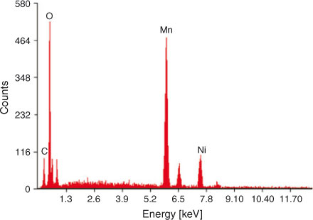
The composition of LiNi0.5Mn1.5O4 was analysed by energy dispersive X-ray spectroscopy (EDX) and inductively coupled plasma spectroscopy (ICP). It can be seen from the EDX spectrum that nickel, manganese, and oxygen are present in the sample in the required amounts There is a small carbon peak, confirming the presence of carbon in the sample as a residue of the organic precursor. This carbon is beneficial for the product and results in improved electrical conductivity. The elemental composition of the sample analysed by EDX and ICP analysis is summarized in Table 2. The EDX spectrum (Fig. 5) is in close agreement with already published data.[55] The characteristic peaks of the Mn, Ni, O, and C are present at their respective position in the EDX spectrum. The slight deviation of the composition from theoretical values is an indication of the disordered structure of the product. Results of the ICP and EDX analysis are in close agreement.
|
|
Specific Surface Area Analysis
The sample was degassed at 150°C for 2 h under a nitrogen atmosphere. Brunauer, Emmet, Teller (BET) and Langmuir surface areas of the product were found to be 13 and 15.2 m2 g–1 respectively. The BET surface area is higher than the previously reported data of 0.5 to 7 m2 g–1.[56–58] This enhanced BET surface area is the result of the nanosize of the particles and porous structure of the material. The large surface area provides a higher reaction surface, which results in an improved charge–discharge performance of the material.
Electrical Conductivity Studies
The electrical conductivity of the LiNi0.5Mn1.5O4 was measured by two-point conductivity measurements using a Keithey 2001 digital multimeter. The electrical conductivity of the sample was found to be 5.23 × 10⁻⁴ S cm–1. This value is higher than for conventional LiNi0.5Mn1.5O4 with an electrical conductivity of 1.12 × 10⁻⁵ S cm–1.[59] This higher electrical conductivity is the result of the nanocrystalline nature and better contact within particles. It is also well known that organic precursors produce carbon impurities in the product, which enhance the electrical conductivity of the sample. Carbon is present in the product as indicated in the EDX analysis.
Discharge Behaviour
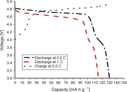
The electrochemical performance of the synthesized LiNi0.5Mn1.5O4 was evaluated in a coin-type 2025-size cell. The electrical performance of the material is summarized in Table 3. The cell was charged–discharged at 0.2 C to confirm the first-cycle capacity and cycle life studies. Cells were charged at 0.2 C and discharged at 1, 5, and 20 C to check the high-rate discharge performance. Previous literature indicates that there are two plateaus in the discharge curve of LiNi0.5Mn1.5O4. The first plateau at ~4.7 V is due to the redox couple Ni2+/Ni4+. This is the desired plateau due to high cell output. The second plateau at ~4V is due to the presence of Mn+3 ions as an impurity in the sample. It is desired that manganese should be in the +4 oxidation state because Mn3+ is unstable and cause dissolution of the manganese ions and destabilization of the structure.[25,29] The 4.1-V plateau is more pronounced in samples prepared by solid-state reactions.[30,31] These reactions require high temperatures and prolonged heating times with intermediate grinding. The process has manifold problems in synthesizing and obtaining a pure product. At high temperature (~800°C), LiNi0.5Mn1.5O4 loses oxygen from the crystal lattice and Mn4+ is converted into Mn3+, thus resulting in the development of the second undesired plateau at 4.1 V.

|
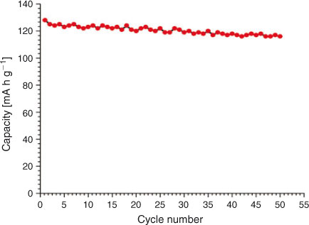
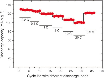
The charge–discharge curves of LiNi0.5Mn1.5O4 between 3.5 and 4.95 V at 0.2 C are shown in Fig. 6. The product exhibits almost a flat 4.7-V discharge curve at 0.2 C. At the end of the discharge, a small 4-V plateau is observed. The discharge capacity due to the 4.7-V plateau is more than 90 % at 0.2 C and more than 94 % at a 1-C discharge rate, indicating a very small amount of Mn3+ in the crystal structure. This is a desired result and much better than the previous results with 14 to 20 % 4-V plateau.[23,36] Discharge capacity reaches 130 mA h at 0.2 C, which is 8 % greater than the already reported results.[23] With cycling, a slight decrease in the discharge capacity is observed, which is common owing to the reaction of the product with electrolyte.[4] The cell delivers more than 94 % capacity after 50 cycles. The capacity remains almost stable after a slight initial loss in first-cycle capacity. The discharge capacity is greater than 120 mA h g–1 even after 50 cycles. Fig. 7 shows the variation in discharge capacity at different loads. First-cycle capacity at 0.2 C reaches 130 mA h g–1, which decreases slightly with cycling at 0.2 C. There is a slight decrease in discharge capacity at 0.5 C, which remains stable for five cycles. Performance at 1, 5, 10, and 20 C is stable and the cell recovers to original capacity when cycled at 0.2 C (Fig. 8). This improved performance is the result of the high electrical conductivity and porous structure of the material.
|
|
|
Conclusion
High-voltage transition metal-doped lithium manganates are potential cathode material for future lithium-ion batteries for electric vehicles and communication devices. Nickel-doped LiNi0.5Mn1.5O4 has a high cell potential of 4.8 V and high energy and power densities. Preparation of phase-pure LiNi0.5Mn1.5O4 is a challenging task. The conventional solid-state synthesis method requires prolonged heating at high temperature, which results in oxygen loss from the crystal lattice and causes loss of cell performance. In this study, a low-temperature synthesis route was demonstrated for the synthesis of LiNi0.5Mn1.5O4. Cyclohexylamine was used as precipitating agent and the resulting organic precursor decomposed at low temperate to produce highly crystalline phase-pure product. The prepared powder has high electrical conductivity and exhibits superior discharge behaviour. First-cycle discharge capacity reaches 130 mA h g–1 and remains stable up to 50 cycles. The synthesized material is stable at high discharge rates and no performance loss occurs on cycling at 20 C.
References
[1] K. S. Lackner, in Issues in Environmental Science and Technology, Carbon Capture and Storage (Eds R. E. Hester and R. M. Harrison) 2010, Vol. 29, pp. 1–2 (Royal Society of Chemistry: Cambridge, UK).[2] R. York, Nature. Clim. Change 2012, 2, 441.
| Crossref | GoogleScholarGoogle Scholar |
[3] C. F. Ehrfeld, Renewable Energy Resources: a Chance to Combat Climate Change, 2009, Ch. 1, pp. 1–5 (Kluwer Law International: Frederick, MD).
[4] Q. Su, G. Zhang, J. Lai, S. Feng, W. Shi, World Electric Vehicle J. 2010, 4, 000128.
[5] N. Briguglio, L. Andaloro, M. Ferraro, V. Antonucci, in Fuel Cell Hybrid Electric Vehicles, Electric Vehicles: the Benefits and Barriers (Ed. S. Selu) 2011, Ch. 6, pp. 94–98 (InTech: Rijeca, Croatia).
[6] K. Young, C. Wang, L. Y. Wang, K. Strunz, in Electric Vehicle Integration into Modern Power Networks, Power Electronics and Power Systems (Eds R. G. Valle and J. A. P. Lopes) 2013, Ch. 2, pp. 15–57 (Springer Science + Business Media: New York, NY).
[7] M. G. Kim, J. Cho, Adv. Funct. Mater. 2009, 19, 1497.
| Crossref | GoogleScholarGoogle Scholar | 1:CAS:528:DC%2BD1MXnt1CmtrY%3D&md5=edfd1dbd785295ed1103c9b4337d307aCAS |
[8] M. Jo, Y. K. Lee, K. M. Kim, J. Cho, J. Electrochem. Soc. 2010, 157, A841.
| Crossref | GoogleScholarGoogle Scholar | 1:CAS:528:DC%2BC3cXmvVGqs78%3D&md5=4a2318d4a139ba329485dea378205f14CAS |
[9] J. Yang, X. Han, X. Zhang, F. Cheng, J. Chen, Nano Research 2013, 6, 679.
| Crossref | GoogleScholarGoogle Scholar | 1:CAS:528:DC%2BC3sXhsVCis7nO&md5=a24ca4b23b55a4cd9b9177748c2b1486CAS |
[10] D. Guyomard, J. M. Tarascon, Adv. Mater. 1994, 6, 408.
| Crossref | GoogleScholarGoogle Scholar | 1:CAS:528:DyaK28XjtlKju7w%3D&md5=1da4ad2da365e92dada5869a557b5da0CAS |
[11] M. Yoshio, R. J. Broad, A. Kozawa, in Lithium-ion Batteries: Science and Technology (Eds M. Yoshio, R. J. Brodd and A. Kozawa) 2009, Ch. 2, pp. 9–49 (Springer Science + Business Media: New York, NY).
[12] J. B. Goodenough, in Lithium Ion Batteries: Fundamentals and Performance (Eds M. Wakihara and O. Yamamoto) 1998, Ch. 1, pp. 1–25 (Willey-VCH Verlag GmBH: Weinheim).
[13] C. Julien, S. Ziolkiewicz, M. Lemaland, M. Massot, J. Mater. Chem. 2001, 11, 1837.
| Crossref | GoogleScholarGoogle Scholar | 1:CAS:528:DC%2BD3MXkslSlu7k%3D&md5=a2f2d50f6b17db90bf301e18f4cf45a8CAS |
[14] E. N. Zhecheva, M. Y. Gorovaand, R. K. Stoyanova, J. Mater. Chem. 1999, 9, 1559.
| Crossref | GoogleScholarGoogle Scholar | 1:CAS:528:DyaK1MXjvFCgtbg%3D&md5=2a3bf827ee156c233317a55e2a3e4aabCAS |
[15] S. H. Ju, D. Y. Kim, E. B. Jo, Y. C. Kang, J. Mater. Sci. 2007, 42, 5369.
| Crossref | GoogleScholarGoogle Scholar | 1:CAS:528:DC%2BD2sXnslygur8%3D&md5=fd52d2323f59e61e5e20b47ca0b8cc67CAS |
[16] S. T. Myung, S. Komaba, N. Kumagai, H. Yashiro, H. T. Chung, T. H. Cho, Electrochim. Acta 2002, 47, 2543.
| Crossref | GoogleScholarGoogle Scholar | 1:CAS:528:DC%2BD38XktFaqsr8%3D&md5=12f2ab50062443dd86e048586e7153afCAS |
[17] Y. S. Lee, Y.-K. Sun, S. Ota, T. Miyashita, M. Yoshio, Electrochemichem. Commun. 2002, 4, 989.
| Crossref | GoogleScholarGoogle Scholar | 1:CAS:528:DC%2BD38Xoslalu7s%3D&md5=20ce9e9f271d27551317c14bc09d87bbCAS |
[18] B. Cheng, X. Chen, X. Li, H. Xu, J. Yong, Y. Qiang, Int. J. Electrochem. Sci. 2012, 7, 6453.
| 1:CAS:528:DC%2BC38XhtVenurrM&md5=6f91a06e73134d8037a4fa2b6983b5e0CAS |
[19] P. Arora, B. Popov, R. E. White, J. Electrochem. Soc. 1998, 145, 807.
| Crossref | GoogleScholarGoogle Scholar | 1:CAS:528:DyaK1cXhsFWltb8%3D&md5=43855541d324abde0a2b07e5fb795393CAS |
[20] S. Lee, Y. Cho, H. K. Song, K. T. Lee, J. Cho, Angew. Chem. Int. Ed. 2012, 51, 8748.
| Crossref | GoogleScholarGoogle Scholar | 1:CAS:528:DC%2BC38XhtFClsrfN&md5=6fbad3566ddf3a2af1cb97bbb7fd7a23CAS |
[21] D. K. Kim, P. Muralidharan, H. W. Lee, R. Ruffo, Y. Yang, C. K. Chan, H. Peng, R. A. Huggins, Y. Cui, Nano Lett. 2008, 8, 3948.
| Crossref | GoogleScholarGoogle Scholar | 1:CAS:528:DC%2BD1cXhtFygtL3N&md5=bfa752f2daacaab7636d7eb7c6150c8aCAS |
[22] A. Iqbal, Y. Iqbal, L. Chang, S. Ahmed, Z. Tang, Y. Gao, J. Nanopart. Res. 2012, 14, 1206.
| Crossref | GoogleScholarGoogle Scholar | 1:CAS:528:DC%2BC3sXhsVWhsrvP&md5=9b47eade4917186200d202ca5cddbb77CAS |
[23] L. Guoqiang, in Lithium Ion Batteries – New Developments (Ed. I. Belharouak) 2012, pp. 83–100 (InTech Publications: Rijeka, Croatia).
[24] J. H. Kim, Y. J. Hong, B. K. Park, Y. C. Kang, J. Ind. Eng. Chem. 2013, 19, 1204.
| 1:CAS:528:DC%2BC3sXktlKqtA%3D%3D&md5=9a936ac70019e09890bc47235feb96f4CAS |
[25] K. M. Shaju, P. G. Bruce, Dalton Trans. 2008, 5471.
| Crossref | GoogleScholarGoogle Scholar | 1:CAS:528:DC%2BD1cXht1SlsbzI&md5=68708a5409b476b2d36e8f7cd9bd71bfCAS | 19082030PubMed |
[26] Z. Zhao, J. Ma, H. Tian, L. Xie, J. Zhou, P. Wu, Y. Wang, J. Tao, X. Zhu, J. Am. Ceram. Soc. 2005, 88, 3549.
| Crossref | GoogleScholarGoogle Scholar | 1:CAS:528:DC%2BD2MXhtlalurzO&md5=506560627cfa8c0e9e4cbade8f8fa3d4CAS |
[27] H. Konishi, K. Suzuki, S. Taminato, K. Kim, S. Kim, J. Lim, M. Hirayama, R. Kanno, J. Power Sources 2014, 246, 365.
| Crossref | GoogleScholarGoogle Scholar | 1:CAS:528:DC%2BC3sXhsFCqt7zE&md5=5bd366288ba7ce6192515aba247818f8CAS |
[28] T. Ohzuku, S. Takeda, M. Iwanaga, J. Power Sources 1999, 81–82, 90.
| Crossref | GoogleScholarGoogle Scholar |
[29] H. Y. Xu, S. Xie, N. Ding, B. L. Liu, Y. Shang, C. H. Chen, Electrochim. Acta 2006, 51, 4352.
| Crossref | GoogleScholarGoogle Scholar | 1:CAS:528:DC%2BD28XkvVahu78%3D&md5=67d60e18b8755608051d19444b4ffb32CAS |
[30] X. Wu, S. B. Kim, J. Power Sources 2002, 109, 53.
| Crossref | GoogleScholarGoogle Scholar | 1:CAS:528:DC%2BD38XjvFGhtLo%3D&md5=725903bf72ab1c0bbe4daee938b649fbCAS |
[31] Q. Zhong, A. Bonakdarpour, M. Zhang, Y. Gao, J. R. Dahn, J. Electrochem. Soc. 1997, 144, 205.
| Crossref | GoogleScholarGoogle Scholar | 1:CAS:528:DyaK2sXhtFemtLs%3D&md5=bb1b00a8b77be84dff8e6f054f591fd9CAS |
[32] Y. Idemoto, H. Narai, N. Koura, J. Power Sources 2003, 119–121, 125.
| Crossref | GoogleScholarGoogle Scholar |
[33] H. Seyyedhosseinzadeh, F. Mahboubi, A. Azadmehr, Electrochim. Acta 2013, 108, 867.
| Crossref | GoogleScholarGoogle Scholar | 1:CAS:528:DC%2BC3sXhs1eqtLjP&md5=617727f4935b30c3fca8e92462f85f8eCAS |
[34] X. Wu, S. B. Kim, J. Power Sources 2002, 109, 53.
| Crossref | GoogleScholarGoogle Scholar | 1:CAS:528:DC%2BD38XjvFGhtLo%3D&md5=725903bf72ab1c0bbe4daee938b649fbCAS |
[35] R. Alcántara, M. Jaraba, P. Lavela, J. L. Trado, Electrochim. Acta 2002, 47, 1829.
| Crossref | GoogleScholarGoogle Scholar |
[36] S. H. Park, S. W. Oh, S. T. Myung, Y. C. Kang, Y. K. Sun, Solid State Ion. 2005, 176, 481.
| Crossref | GoogleScholarGoogle Scholar | 1:CAS:528:DC%2BD2MXitVSmsQ%3D%3D&md5=140182b10b9165f156bad19ae8015b25CAS |
[37] J. H. Kim, S. T. Myung, Y. K. Sun, Electrochim. Acta 2004, 49, 219.
| Crossref | GoogleScholarGoogle Scholar | 1:CAS:528:DC%2BD3sXptFGltrs%3D&md5=b4ae6a586afcc7c354a55edcd3927ed2CAS |
[38] M. G. Lazarraga, L. Pascual, H. Gadjov, D. Kovacheva, K. Petrov, J. M. Marilla, R. M. Rojas, M. A. Martin-Luengo, J. M. Rojo, J. Mater. Chem. 2004, 14, 1640.
| Crossref | GoogleScholarGoogle Scholar | 1:CAS:528:DC%2BD2cXjvFaqs7Y%3D&md5=cf400c143e873ab0dc211ae3b92d2cc5CAS |
[39] H. S. Fang, Z. Wang, X. Li, H. Guo, W. Peng, Mater. Lett. 2006, 60, 1273.
| Crossref | GoogleScholarGoogle Scholar | 1:CAS:528:DC%2BD28XhtV2ksLs%3D&md5=4cd80f93a838fe6c9c0eeef7003d7cc4CAS |
[40] H. Fang, Z. Wang, B. Zhang, X. Li, G. Li, Electrochem. Commun. 2007, 9, 1077.
| Crossref | GoogleScholarGoogle Scholar | 1:CAS:528:DC%2BD2sXkslahtL4%3D&md5=b3b3b067a44e51be0c62ba9a627e158bCAS |
[41] S. H. Park, S. W. Oh, S. H. Kang, I. Belharouak, K. Amine, Y. K. Sun, Electrochim. Acta 2007, 52, 7226.
| Crossref | GoogleScholarGoogle Scholar | 1:CAS:528:DC%2BD2sXosFaksr4%3D&md5=b231d38e22f50c003b03ba45c96b3ba0CAS |
[42] S. H. Park, S. W. Oh, C. S. Yoon, S. T. Myung, Y. K. Sun, Electrochem. Solid-State Lett. 2005, 8, A163.
| Crossref | GoogleScholarGoogle Scholar | 1:CAS:528:DC%2BD2MXis1Wjt78%3D&md5=ee0334bc7063ae2b64ac11a94bf4ed3aCAS |
[43] Q. Zhong, A. Bonakdarpour, M. Zhang, Y. Gao, J. R. Dahn, J. Electrochem. Soc. 1997, 144, 205.
| Crossref | GoogleScholarGoogle Scholar | 1:CAS:528:DyaK2sXhtFemtLs%3D&md5=bb1b00a8b77be84dff8e6f054f591fd9CAS |
[44] Y. Idemoto, H. Narai, N. Koura, J. Power Sources 2003, 119–121, 125.
| Crossref | GoogleScholarGoogle Scholar |
[45] T. Ohzuku, K. Ariyoshi, S. Yamamoto, J. Ceram. Soc. Jpn. 2002, 110, 501.
| Crossref | GoogleScholarGoogle Scholar | 1:CAS:528:DC%2BD38XksFGhsLg%3D&md5=1b8e3118a6bf487e90d009dbb01dcb2cCAS |
[46] Y. Terada, K. Yasaka, F. Nishikawa, T. Konishi, M. Yoshio, I. Nakai, J. Solid State Chem. 2001, 156, 286.
| Crossref | GoogleScholarGoogle Scholar | 1:CAS:528:DC%2BD3MXptlGgtg%3D%3D&md5=ecd4c1571f1ba4a894554823684be148CAS |
[47] H. Fang, L. Li, G. Li, J. Power Sources 2007, 167, 223.
| Crossref | GoogleScholarGoogle Scholar | 1:CAS:528:DC%2BD2sXjvV2rs7o%3D&md5=3708c726634026fc557ed816f2d71cbcCAS |
[48] M. G. Lazarraga, L. Pascual, H. Gadjov, D. Kovacheva, K. Petrov, J. M. Amarilla, R. M. Rojas, M. A. Martin-Luengo, J. M. Rojo, J. Mater. Chem. 2004, 14, 1640.
| Crossref | GoogleScholarGoogle Scholar | 1:CAS:528:DC%2BD2cXjvFaqs7Y%3D&md5=cf400c143e873ab0dc211ae3b92d2cc5CAS |
[49] Y. Gao, K. Myrtle, Phys. Rev. 1996, B54, 16670.
[50] X. Zhang, F. Cheng, J. Yang, J. Chen, Nano Lett. 2013, 13, 2822.
| Crossref | GoogleScholarGoogle Scholar | 1:CAS:528:DC%2BC3sXnslent7s%3D&md5=8a026323e2a207ed16aee5a9f5520f50CAS | 23679068PubMed |
[51] Q. Zhong, A. Bonakdarpour, M. Zhang, Y. Gao, J. R. Dahn, J. Electrochem. Soc. 1997, 144, 205.
| Crossref | GoogleScholarGoogle Scholar | 1:CAS:528:DyaK2sXhtFemtLs%3D&md5=bb1b00a8b77be84dff8e6f054f591fd9CAS |
[52] Q. A. Acton, Metals – Advances in Research and Applications 2011, Ch. 1, pp. 47–49 (Scholarly Editions: Atlanta, GA).
[53] S. Ullah, A. Badshah, F. Ahmed, R. Raza, A. A. Altaf, R. Hussain, Int. J. Electrochem. Sci. 2011, 6, 3801.
| 1:CAS:528:DC%2BC3MXht1Chsr%2FP&md5=95a36281570f4c6d69c890a76e0e8de7CAS |
[54] N. M. Daraz, Int. J. Electrochem. Sci. 2013, 8, 5203.
[55] X. Fang, N. Ding, X. Y. Feng, Y. Lu, C. H. Chen, Electrochim. Acta 2009, 54, 7471.
| Crossref | GoogleScholarGoogle Scholar | 1:CAS:528:DC%2BD1MXht1WiurbK&md5=37e1240aeec392a9a472df363ceaf953CAS |
[56] S. R. Li, C. H. Chen, J. Camardese, J. R. Dahn, J. Electrochem. Soc. 2013, 160, A1517.
| Crossref | GoogleScholarGoogle Scholar | 1:CAS:528:DC%2BC3sXhsV2itr%2FO&md5=02a95d41a0793050cafda00d675cd410CAS |
[57] M. S. Kuthanapillil, P. G. Bruce, Dalton Trans. 2008, 40, 5471.
[58] A. V. Potapenko, S. I. Chernukhin, I. V. Romanova, K. S. Rabadanov, M. M. Gafurov, S. A. Kirillov, Proceedings of the International Conference Nanomaterials: Applications and Properties 2013, Vol. 2, p. 04NEA06 (Sumy State University: Sumy, Ukraine)
[59] X. Hao, B. M. Bartlett, J. Electrochem. Soc. 2013, 160, A3162.
| Crossref | GoogleScholarGoogle Scholar | 1:CAS:528:DC%2BC3sXptlKqsL0%3D&md5=2e009a4d9034756cd1eb3c3e0bdc3c46CAS |